Introduction of Some Extruder Auxiliaries
- Updated on February 6, 2022
As an auxiliary machine for an extruder, the main function is to improve the quality of the extruded melt, reduce the production cost, and facilitate automated operations. Extruder auxiliaries are usually general-purpose, but are also modified or specialized depending on the product. Reasonable selection should be made according to the actual situation when selecting. Several common extruder auxiliary devices are introduced below.
Extruder Feeding System
Dryer for Extruder Feeder
Install a hot air dryer directly on the extruder hopper, as shown below. The raw material is automatically fed into the hopper by the feeding system, and the hot air heated by the heater is forced to blow through the raw material from the bottom of the hopper by the fan, so that the raw material can be dried. The hot air may contain a certain amount of humidity, which should be removed before being sent to the dryer. Usually, the air is passed through a silica gel dehumidifier to absorb the moisture in the air, thereby improving the efficiency of the dryer and reducing the drying time by about 50%.
Magnetic Separator for Extrusion Line
When feeding into the hopper, small metal particles such as metal fragments, bolts, nuts, small screws, etc. are often mixed in for various reasons, resulting in damage to the extruder screw and barrel. Magnetic separators are the most common ferrous removal devices. It is composed of a strong magnetic grid, which is installed in the hopper. When the raw material passes through the grid, the iron mixed in the raw material is adsorbed in the magnetic tube. After a certain period of time, the grid is taken out from the hopper to remove the attached iron, and then it is loaded into the hopper again. In addition, in order to remove non-ferrous metals such as stainless steel, brass and aluminum, metal removal devices with high frequency magnetic lines of force can be used.
Extruder Metering Device
The metering device is installed on the extruder to measure resin, pigment, lubricant, foaming agent, etc. respectively.
1. Metering unit for blending. This scheme is shown below. It is usually used in the blending and extrusion of recycled material 1 and base raw material 2. The metering accuracy does not need to be particularly high. The metering intermittent valve is directly installed at the entrance of the hopper, and the valve body can be set according to the setting. Periodically move to adjust the admixture ratio. When conveying two raw materials, the raw materials fall into the hopper alternately layer by layer, and the admixtures in the hopper can be fully mixed.
2. Metering unit for additives.As shown below, in the metering device, the main raw material 1 directly enters the hopper without being metered, and the additive (auxiliary agent) 2 enters the hopper through the metering screw. It seems that the main material 1 is not metered, but in fact the flow of the material from the extruder is constant during production. Therefore, the additive 2 will be added in proportion according to the output of the extruder, and the added amount is realized by changing the speed of the metering screw. The mixture in the hopper enters the extruder after being stirred by the hopper agitator.
If multiple additives are required, the number of screw metering devices will be increased. In the multi-component metering device both additives and base materials need to be metered, and the metering device has nothing to do with the extruder. As shown below each metering ratio is determined by the rotational speed of the metering screw or the size of the barrel.
Conveyors and Feeders
The conveyor and the feeder are collectively referred to as the feeding system.
Screw conveyor. It is divided into: rigid screw rotating in a rigid casing and flexible spring rotating in soft metal or plastic tube. They both generate axial force and centrifugal force through high-speed rotation of the screw shaft and spring, so that the raw material is pushed, lifted and fed into the hopper.
The screw conveyor can transport granular materials as well as powder materials. The conveying distance of the screw conveyor is limited. If the feeding distance is long, multiple screw conveyors can be used in series, and one conveyor can also feed multiple extruders. The scheme below shows several feeding methods.
Force feeder. It can be directly installed in the extruder hopper or in the feeding port, so that the raw material is forced into the extruder under the push of external pressure. This kind of device is most suitable for raw materials with small bulk density. When the bulk density of the raw material is lower than 0.3kg/dm3, a forced feeder should be installed.There are two types of forced feeders, namely vertical feeders and horizontal feeders, as shown below.
The feeder is driven by a DC motor, and an overload protection circuit is set to prevent damage to the feeder when the material flow pressure increases or the feed port is blocked. The feeding screw of the vertical feeder is tapered at the feeding port. By adjusting the axial gap, it can transport raw materials with different bulk densities, and the delivery volume is high. The horizontal feeder has a small conveying capacity and can be used for mixing and storing materials, and is only suitable for installation on a single-screw extruder.
Feeder for twin screw extruder . A twin-screw extruder must use a metering device as shown below. It controls the feeding amount by controlling RPM of the feeding screw in the feeder. The feeding of the single-screw extruder does not have strict requirements on quantitativeness, but the twin-screw extruder does. The feeding amount of the twin-screw extruder has a direct impact on the shear rate, material temperature and pressure distribution. When the screw is working, the screw groove is not completely filled with materials. As long as the filling condition of the material in the screw groove is controlled, the shear rate can be controlled so as to control the output of the extrusion. The twin-screw is forced to convey the material by the principle of positive displacement pump. The instantaneous extrusion volume should be strictly consistent with the feeding rate, otherwise it will affect the extrusion stability and dimensional tolerance of final products.
In addition, in order to control the load on the drive system and bearings, dosing is also necessary, especially for hard (PA) and high-viscosity materials (PVC).
Pneumatic conveying system. It mainly includes pressure feeding type and suction type. The pressure feeding device is a compressed air sent by a blower to blow the raw materials into the pipeline at a pressure of 0.2-0.6MPa, and then enter the hopper after passing through the cyclone separator set in the hopper. This method is only suitable for the conveying of granular materials. The suction feeding device is the negative pressure formed by the induced draft fan in the hopper, which automatically closes the discharge valve and sucks the raw materials into the hopper. Then the discharge valve opens and the raw material falls into the large hopper with its gravity. Thus a feeding cycle is completed and repeated until the large hopper is full and the discharge valve cannot be opened. The feeding process can be automatically carried out over and over again through the monitoring and alarm device. This method is suitable for conveying granular materials, but also powder materials.
These two methods can form a single-unit feeding system and a multi-unit feeding system. The single-unit feeding system is set up with an independent conveying pipeline for each extruder; the multi-component feeding system is used for conveying the same raw materials of multiple extruders, sharing one air source, and a control center can be set to realize group control operation and all data are processed by the microcomputer.
Breaker Plate
The breaker plate of the extruder is literally called multi-hole plate. It is arranged in the transition area between the screw head and the die, and a filter screen is placed on the breaker plate. Its function includes: 1. To change the melt flow from rotary motion to linear motion; 2. To prevent unmelted particles from entering the mold and filter out impurities; 3. To increase the melt pressure of the extruder head, make the product compact, further uniform plasticization, and improve the plasticization quality. However, when extruding materials with high viscosity and poor thermal stability (such as PVC), filters are normally not used, or even breaker plates are not used. The distance between breaker plate and the screw tips should not be too large, otherwise it will easily cause material accumulation and decompose the heat-sensitive plastics; if the distance is too small, the material flow will be unstable, which is not good for the quality of the product. So the distance recommended is 0.1D (D is the diameter of the screw).
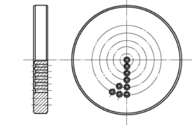
There are many different forms of breaker plate, and the most used one is flat plate-shaped as shown below, which has a simple structure and is convenient to manufacture. In order to make the flow rate of the material consistent after passing through the dividing plate, the distribution of the holes is often sparse in the middle and dense in the sides. The size of the holes is usually uniform, but there are also different ones. Sometimes the holes in the middle are sparse and large in diameter, so that the resistance in the middle is not too large, so as to avoid the thermal decomposition of the material due to the long residence time.
The size of the hole and the thickness of the plate increase with the increase of the diameter of the screw. The diameter of the hole is generally 2 to 7 mm, and the total area of the hole is usually 30% to 70% of the total area of the breaker plate. The thickness is also determined by the size of the extruder and the size of the pressure it bears, generally about 1/3 to 1/5 of the inner diameter of the barrel. The arrangement of holes is mostly concentric circles, and there are also hexagonal arrangements.
Screen Changer for Extruder
During the plastic extrusion process, the plastic melt will be plasticized and heated for a long time, which will produce residues, plus impurities and unplasticized particles in the raw materials. Once it enters the extrusion mold, it will cause flow channel blockage or product defects, and even cannot be produced normally. In order to eliminate these granular impurities, make the pure melt enter the extrusion die smoothly, and obtain high-quality products, a filter screen must be placed between the extruder screw head and the die, and as the extrusion time continues, more and more dirt filtered will accumulate on the mesh. At this time, the melting pressure will increase and the melt flow will decrease. When the melting pressure exceeds a certain melting pressure, the filter screen will be broken or blocked and become invalid, and the filter screen must be replaced.
Extruder screen changers can be roughly divided into two categories. One is discontinuous screen changer, the melt flow will break by instantaneous interruption or the machine should be stopped during the screen change. The other is continuous screen changer. It can change the screen continuously, automatically, without downtime, and the material flow is not interrupted.
Discontinuous Screen Changer
With discontinuous screen changer, the melt flow will break by instantaneous interruption or the machine should be stopped during the screen change.
There are quite a few forms of this type. Typical ones are: manual gate valve type screen changer, hydraulic blade type screen changer, candle type manual screen changer and so on.
The above two both have the main components with the same function—the double (multi) hole valve plate 1 for filtering the melt. There is always one filter in the flow channel of the melt, and the other filter hole is located in a position where it is easy to replace or clean. The gate valve of the screen changer is by hand to change the position of the two filters, and the aperture is generally less than 80mm. It is mainly used in the occasions where the output is low, the pollution is small, and the screen change time is more than 6 hours. The hydraulic blade type screen changer switches the position of filters by the back and forth movement of the piston rod of the hydraulic system, and the aperture can reach 250mm. The sealing system of these two screen changers is realized by the pressure of the melt on the PTFE sealing ring and the aluminum-bronze sealing ring, and the screen changing time is short, only completed within 1 second or few seconds. However, when the part 1 moves, the melt pressure drops, and it is not easy for the melt to fill the channel immediately. At this time, the material flow will be interrupted instantaneously, and the real continuous operation cannot be realized. This type of screen changer is only suitable for products with large fluctuations in extrusion volume, low precision and low quality, such as thick-walled pipes with large volumes, plates, granulation, color mixing and other products, as well as for two-stage tandem extrusion.
For products such as flat yarn, monofilament, agricultural mulch film, cast film, laminated film, and sheet, if the material is interrupted instantaneously when changing the screen, it needs to be redrawn on the auxiliary machine. Even if the extrusion process is not completely interrupted, the product will be blemished. The screen changer shown below prolongs the screen changing interval by increasing the filter area.
The filter area is 0.1~0.4m3, which is 10~40 times that of other screen changers, and the pressure drop is small. Ultra-fine filter meshes can be used. The purity of the filtered melt is high, but every time the screen is changed, it must be cleaned, assembled, and heated again, which is time-consuming and labor-intensive, and the downtime is long, ranging from half an hour to several hours. The large filter area with large inlet and outlet makes the material is likely to degrade; besides, it has very poor self-cleaning properties.
Continuous Screen Changer for Extruder
The continuous screen changer is a non-stop, continuous and automatic screen changer. The scheme below shows the hydraulic sliding screen changer, which has a greater improvement than the hydraulic blade type screen changer. It is mainly composed of the screen changer body 1, the hydraulic drive system 2 and the shunt filter plate 3. There is filter mesh on the shunt filter plate 3. The filter screen is pasted and pushed along with the filter plate by the cylinder piston rod in the hydraulic system so as to complete the continuous screen changing action. The two sides of the screen changer body are the inlet and outlet of the screen, and an air cooling device is provided to cool and solidify the melt, which is used as a sealing cushion to prevent material leakage between the screen and the screen changer body. The screen changer can operate continuously without interruption of material flow, without pressure drop in the flow runner and without melt leakage.
Melt pressure screen changer shown below is mainly composed of screen changer body 1, heating and cooling system 2, belt-type jointless filter screen 3 and belt-type filter screen box 4 and other components. The belt filter is about 18m long and can be used for thousands of hours, and can be recycled and cleaned for re-use. The clean belt filter drawn from the bin enters the melt filtration channel from one side of the screen changer body, and the filtered dirty mesh comes out from the other side. The belt filter can be moved under melt pressure and the continuous screen change can be realized. The principle is that there are four temperature control zones on the screen changer body through which the belt filter screen passes, and the temperature of the four zones is accurately controlled by the temperature control system with different temperatures. Different temperatures form four different melting pressure areas. When it is necessary to make the belt filter move or not move (that is, to change the screen or not to change the screen), it can be achieved as long as four areas are given different melting pressures. The melt pressure screen changer also adopts self-sealing technology. The inlet and outlet of the belt filter screen on both sides of the screen changer body are cooled, and the melt solidifies to form a film which not only blocks the high temperature melt but also makes the belt filter move smoothly.
Static Mixer for Extruder
The static mixer is an auxiliary equipment of the extruder. It is installed between the extruder and the die to further divide and mix the melt, which is beneficial to increase the screw speed so as to increase the extrusion volume.
The principle of the static mixer is to make mixing elements by alternating and perpendicularly intersecting many right helical and left helical plates, which are fixed in the circular tube. When the melt passes through the mixing element in the circular tube, it is divided into several strands, and then flows along the flow channel formed by the element. The number of multi-split stream strands increases exponentially. The helical axis of the element rotates, and the inversion of the melt leads to radial mixing, which improves the temperature and viscosity inhomogeneity of each component of the melt, especially the radial temperature difference. A heater is installed outside the static mixer tube like the barrel. The working performance of the static mixer is not limited by the screw specification or rotation speed, and the melt flow resistance is small, which has little effect on the production capacity of the extruder. When the radial temperature difference needs to be improved, a static mixer with 6 spiral plates can be selected; when the pigment needs to be dispersed evenly, a static mixer with 9 spiral plates can be selected. Static mixers can be used for extrusion lamination, wire wrapping, blown film, sheet, profile, pipe and foam.
Melt Pump (Gear Pump) for Extruder
In order to stabilize the pressure generated by the melt in the die and to extrude high-precision, high-quality products, a gear pump is often installed between the die and the tooling. It can replace or partially replace the compression section and homogenization section of the extruder to achieve non-fluctuant quantitative extrusion.
The gear pump as a melt metering and conveying device is composed of a pump chamber, a metering gear, a melt inlet, a melt outlet and a transmission system. The pump body needs to be heated. The transmission system is controlled by a silicon rectifier circuit to control the DC motor, which can precisely control the speed of the pump. The pressure at the inlet of the pump can be within a certain range. After the melt enters the tooling at the outlet, the pressure of the melt extruded from the die is constant and can be stabilized within plus or minus 1%. Generally, the melt pump is selected according to the size and output of the extruder, and the speed of the pump is usually between 10 and 40 r/min. By using a melt metering pump to extrude high-quality film with uniform thickness and small thickness tolerance is possible. When used for PA, PET and PP cast films, the output can reach 100-600kg/hr.
Leave us a comment below for a further discussion or contact us for further clarification.